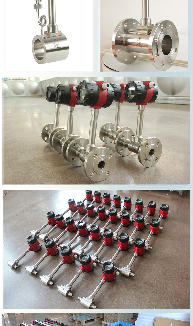


Advantage
1.The measuring element structure of vortex flow meter is simple, firm, and easy to install and maintain. No need for pressure pipes, three valve manifolds, etc., reducing leakage, blockage, and freezing. The measuring element has a simple structure, reliable performance, long service life, and low maintenance.
2.The vortex flow meter has a wide measurement range, and the range ratio can generally reach 1:10. Vortex flow meter with a reasonable caliber has been determined, and the range can reach 20:1.
3.The volumetric flow rate of vortex flow meter is not affected by thermal parameters such as the pressure, temperature, density, or viscosity of the measured fluid, and generally does not require separate calibration. It can measure the flow rate of liquid, gas, and steam.
4.The vortex flow meter has no movable components or throttling components that hinder fluid flow, resulting in minimal pressure loss.
5.The vortex flow meter has high accuracy, up to 1.0%.
6.The vortex flow meter adopts a piezoelectric stress sensor with high reliability and can operate within the operating temperature range of -20 ℃ to+250 ℃, with a maximum temperature resistance of 400 ℃.
7.Vortex flow meters have analog standard signals and digital pulse signal outputs, making it easy to connect with computers and other networks
8.The output is a pulse signal proportional to the flow rate, without zero drift. The pressure loss is small, about 1/4 to 1/2 of the throttle differential pressure flow meter.
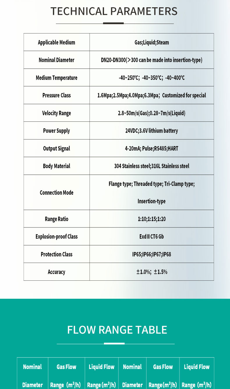
TECHNICAL PARAMETERS
| Applicable Medium | Gas;Liquid;Steam |
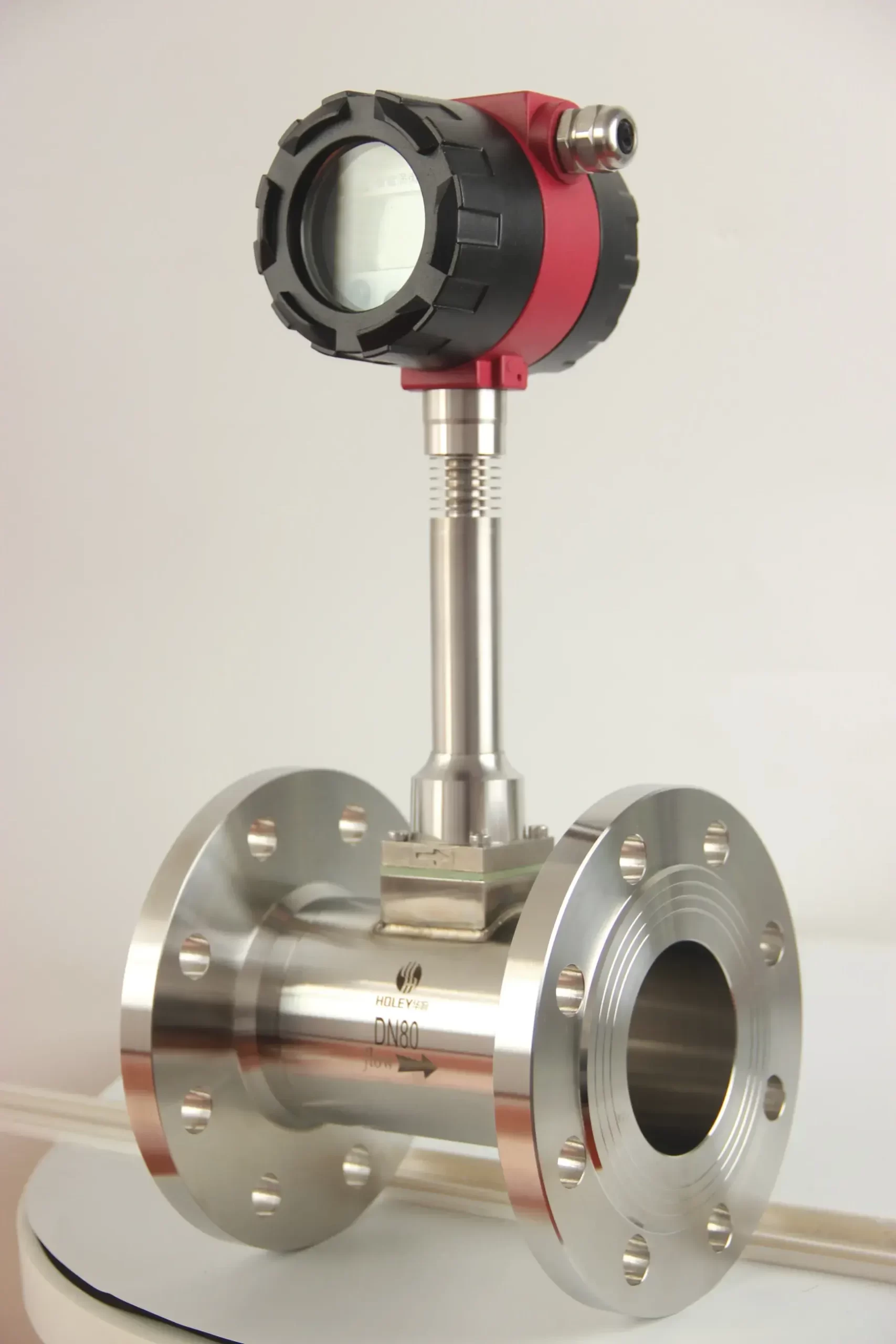
| Nominal Diameter | DN20-DN300(>300 can be made into insertion-type) |
| Medium Temperature | -40~250℃;-40~350℃;-40~400℃ |
| Pressure Class | 1.6Mpa;2.5Mpa;4.0Mpa;6.3Mpa;Customized for special |
| Velocity Range | 2.8~50m/s(Gas);0.28~7m/s(Liquid) |
| Power Supply | 24VDC;3.6V lithium battery |
| Output Signal | 4-20mA; Pulse;RS485;HART |
| Body Material | 304 Stainless steel;316L Stainless steel |
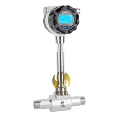
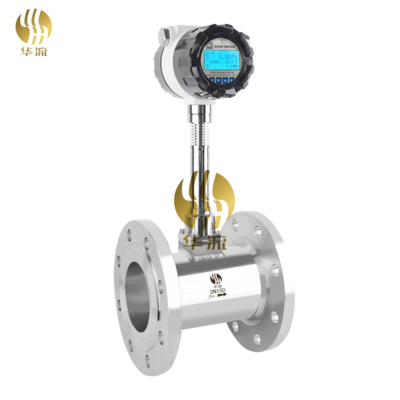
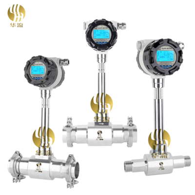
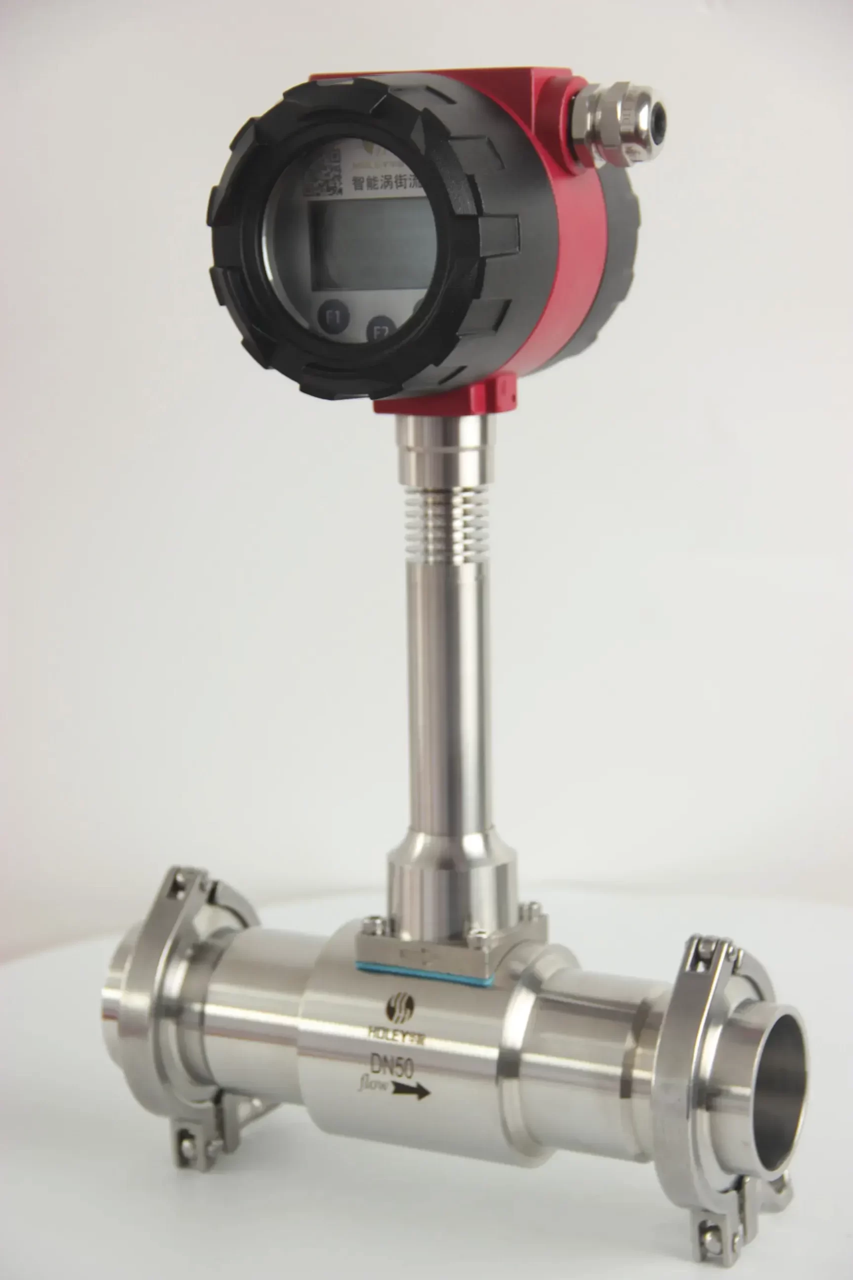
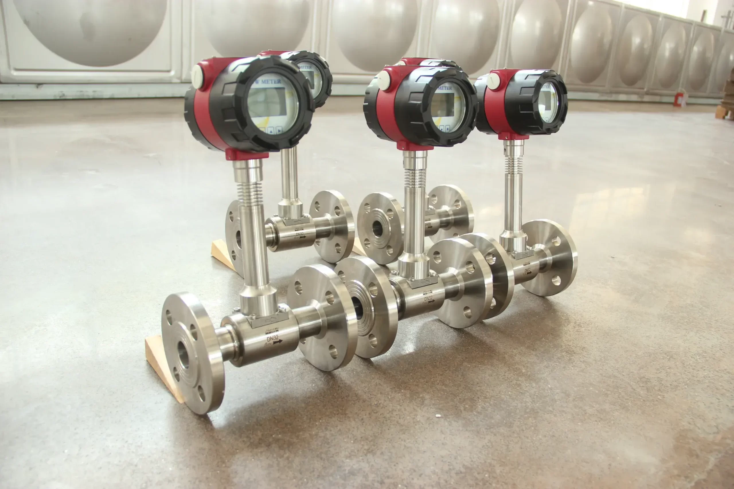
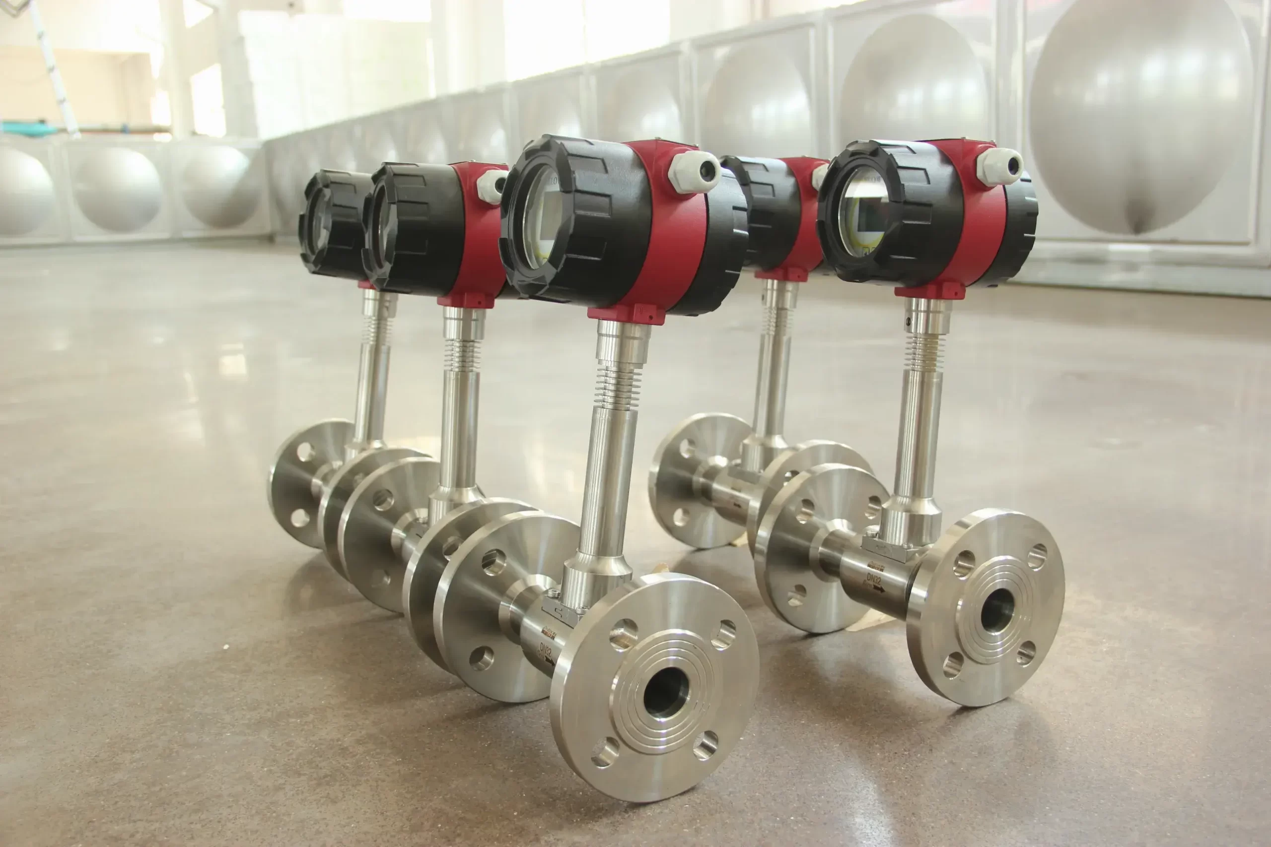
| Connection Mode | Flange type; Threaded type; Tri-Clamp type; Insertion-type |
| Range Ratio | 1:10;1:15;1:20 |
| Explosion-proof Class | ExdⅡCT6 Gb |
| Protection Class | IP65;IP66;IP67;IP68 |
| Accuracy | ±1.0%;±1.5% |
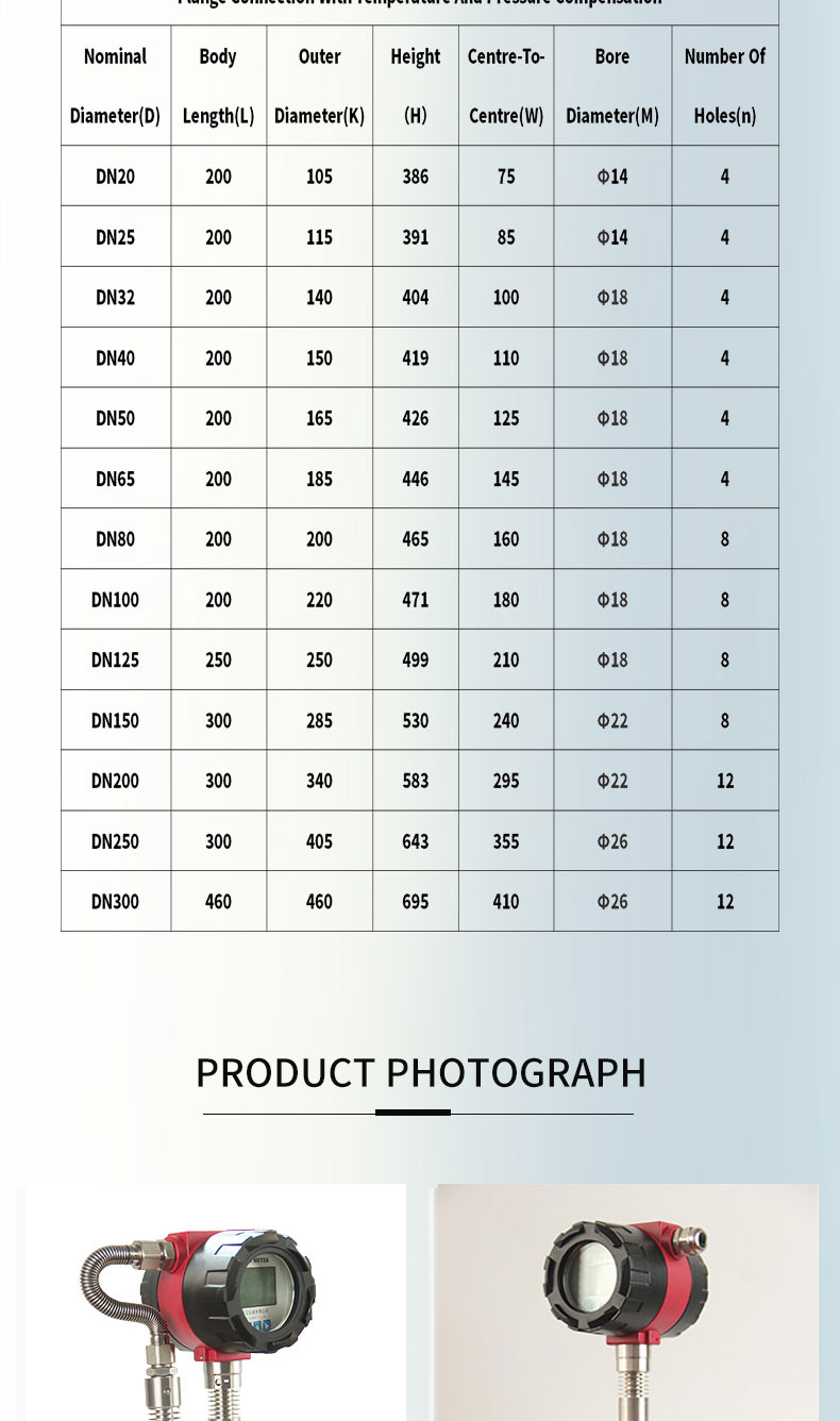
OVERALL DIMENSION TABLE
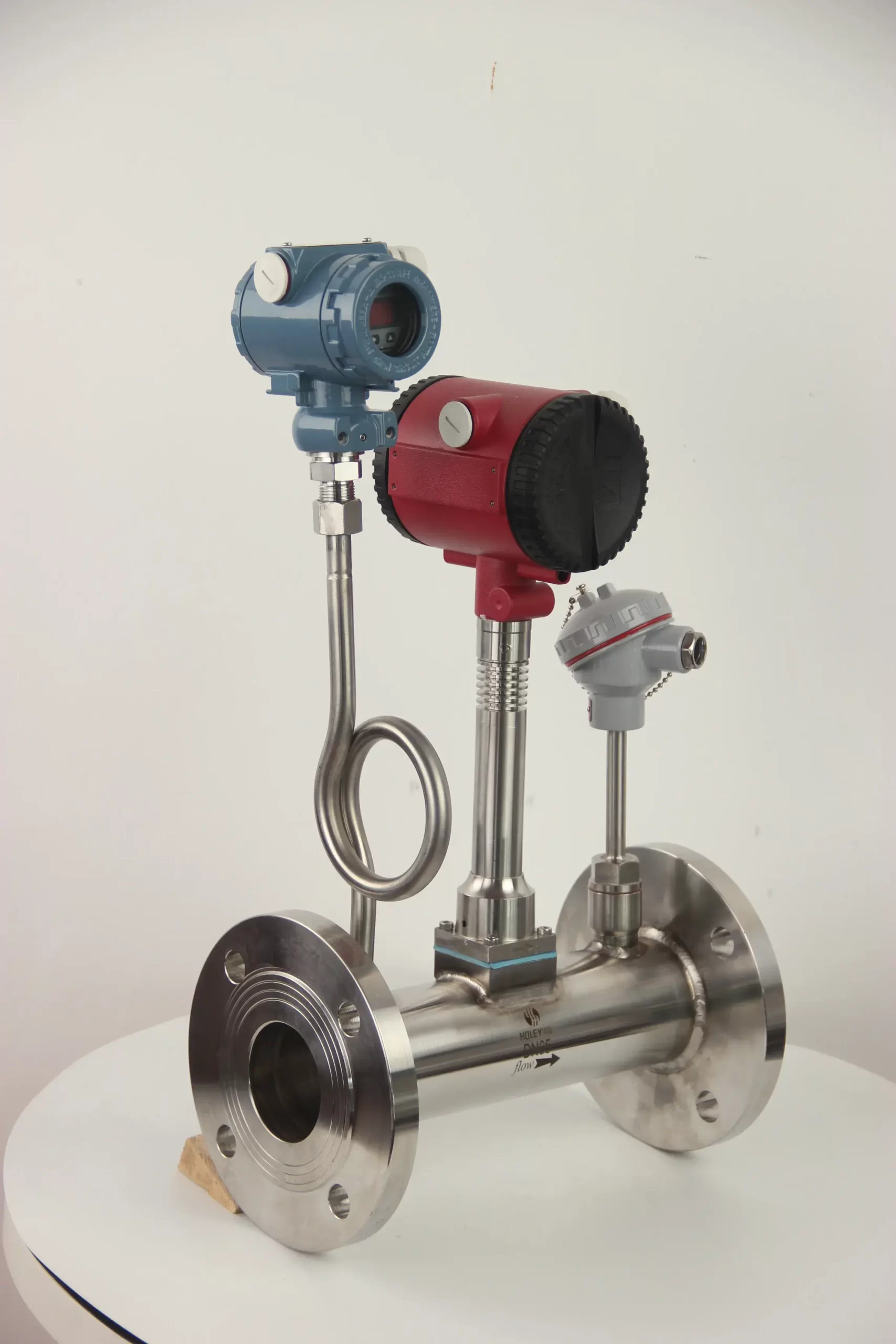
| Flange Connection With Temperature And Pressure Compensation | ||||||
| Nominal Diameter(D) | Body Length(L) | Outer Diameter(K) | Height(H) | Centre-To-Centre(W) | Bore Diameter(M) | Number Of Holes(n) |
| DN20 | 200 | 105 | 386 | 75 | Φ14 | 4 |
| DN25 | 200 | 115 | 391 | 85 | Φ14 | 4 |
| DN32 | 200 | 140 | 404 | 100 | Φ18 | 4 |
| DN40 | 200 | 150 | 419 | 110 | Φ18 | 4 |
| DN50 | 200 | 165 | 426 | 125 | Φ18 | 4 |
| DN65 | 200 | 185 | 446 | 145 | Φ18 | 4 |
| DN80 | 200 | 200 | 465 | 160 | Φ18 | 8 |
| DN100 | 200 | 220 | 471 | 180 | Φ18 | 8 |
| DN125 | 250 | 250 | 499 | 210 | Φ18 | 8 |
| DN150 | 300 | 285 | 530 | 240 | Φ22 | 8 |
| DN200 | 300 | 340 | 583 | 295 | Φ22 | 12 |
| DN250 | 300 | 405 | 643 | 355 | Φ26 | 12 |
| DN300 | 460 | 460 | 695 | 410 | Φ26 | 12 |
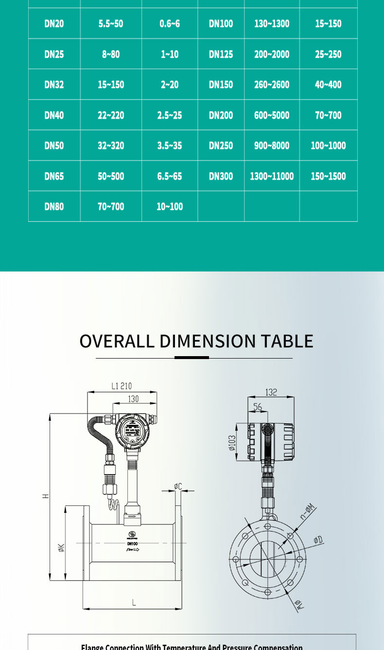
FLOW RANGE TABLE
| Nominal Diameter | Gas Flow Range(m³/h) | Liquid Flow Range(m³/h) | Nominal Diameter | Gas Flow Range(m³/h) | Liquid Flow Range(m³/h) |
| DN20 | 5.5~50 | 0.6~6 | DN100 | 130~1300 | 15~150 |
| DN25 | 8~80 | 1~10 | DN125 | 200~2000 | 25~250 |
| DN32 | 15~150 | 2~20 | DN150 | 260~2600 | 40~400 |
| DN40 | 22~220 | 2.5~25 | DN200 | 600~5000 | 70~700 |
| DN50 | 32~320 | 3.5~35 | DN250 | 900~8000 | 100~1000 |
| DN65 | 50~500 | 6.5~65 | DN300 | 1300~11000 | 150~1500 |
| DN80 | 70~700 | 10~100 |